


In the past, the Frequency
Modulation technique was used widely in radio
transmission but had not been applied to sound
synthesis. In the early 1970s, John Chowning, a composer
and researcher at Stanford University, developed some
important new techniques for music synthesis using FM:
the FM algorithms. In the late 70’s I found myself
exploring FM techniques on the ARP 2600 the analogue
way. By using spring
reverberation between the modulator and carrier, blurring the spectrum, I found FM an
extremely useful technique for creating impressive sonic
structures. The aim of this writing is to find useful
extensions of the FM technique in Kyma. The sine wave
oscillators in these sounds are called “Operators”, OP(n)
in short, like in the algorithms of Yamaha’s DX7. In
these articles, the focus will be on the more practical
side of extensibility applications of FM synthesis.
You can find all of the
Kyma Sounds used here in the
FM Tutorial
archive in the
Community Library
of Symbolic
Sound.
The technical story
behind the FM
Simply put, FM involves two sine waves. One is called
the modulating wave, the other the carrier wave. The modulating wave changes the
frequency of the carrier wave. It can be easiest to visualize, understand, and
hear when the modulator is low frequency. (Open the file FM Basic 1.kym found
in the FM Basic folder and
play the Sound).
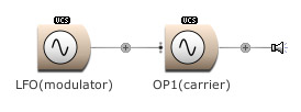
When set on a sine wave, the LFO
modulation creates a vibrato. When the speed of this modulation is raised to
within the audio spectrum, sidebands are obtained. These are complex harmonic
structures (sound characters). These structures are defined by the ratio: the
equation of pitch between the modulator and carrier. The number of harmonics
that make a significant contribution to the spectrum depends on the modulation
index. (Open FM Basic 2.kym).
FM sidebands:
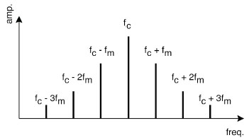
The FM spectrum can be
considered to be made up of a carrier frequency at
fc and an infinite number of sidebands at frequencies fc ± n*fm.
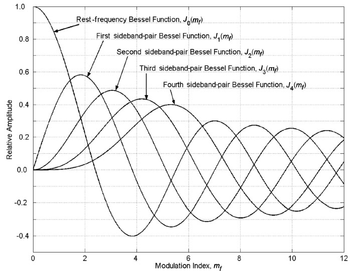
The relative amplitude of a particular sideband at fc ±
n*fm is governed by Jn(I), the Bessel function for the particular
n.
The use of FM equations of an operator can be
combined with one or more FM operators to synthesize different types of complex
waveforms. In our first sound
FM Basic 1
we can explore these functions in pitch ratio and amplitude. If we are
experiencing the changes of timbre, when moving the sliders, we can imagine what
would happen shaping these complex spectra:
- Ratio: 1/1 creates a
sawtooth
wave.
- Ratio: 1/2 creates a
filtered square wave.
- Ratio: 1/3 creates a
33% pulse wave.
- Ratio: 1/4 creates a
square wave,
and so on.

How do we build in control of frequencies and
amplitudes?
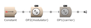
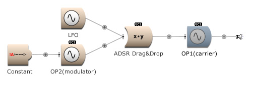
We have to create amplitude modulations. The
product of the
LFO’s
sine wave and
OP2 modulates the
OP1’s
frequency. The modulation of the
LFO
is increasing and decreasing the output of
OP2.
Therefore it sounds like a filter is opened and closed slowly. (Open FM
Basic 3.kym).
What happens if a Multisegment Envelope is used for
modulating OP2’s output? Press the On-button
in the VCS. (Open FM Basic 4.kym).
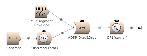
The timbre modulation is as recognizable as an EG
[envelope generator] modulation on a LP [low pass] filter. The
output of the carrier OP1 was constant amplitude. We
can start and modulate it’s amplitude with the same EG as from OP2,
the modulator. Press the On button to hear it. (Open FM
Basic 5.kym).
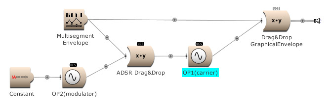
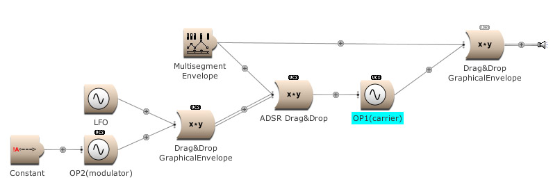
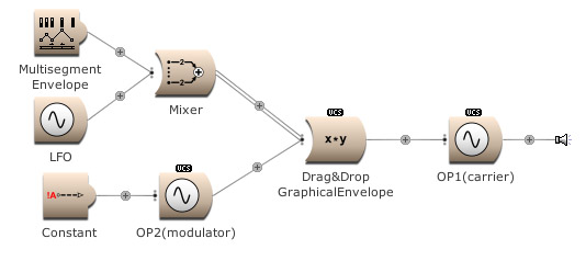
We even can add the
LFO,
from the first amplitude modulation example, and EG energy level to modulate the
input of OP1.
Press the On
button again. (Open FM
Basic 6.kym).
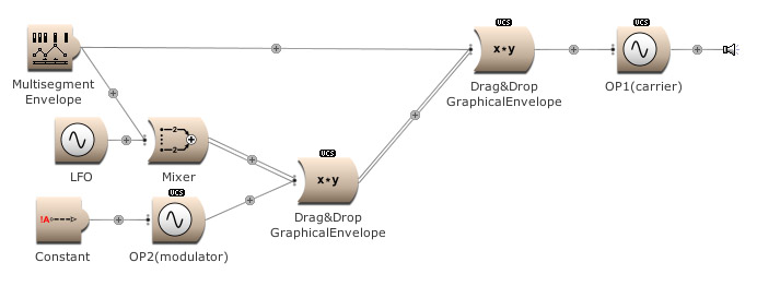
In the next example a
Mixer module
is used to add the outputs from the
Multisegment Envelope
and LFO
to modulate the FM index. Try the
On
button. (Open FM
Basic 7.kym).
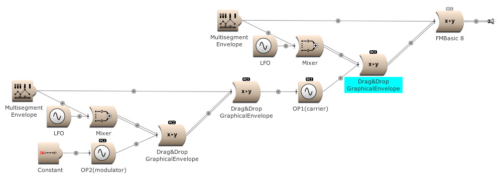
How can an EG, the Multisegment Envelope,
control the amount of modulation of the EG itself and the LFO?
Press On. (Open FM Basic 8.kym).
Adding things together.
For both, carrier and modulator, available amplitude modulators. Press the
On
button again to hear. (Open FM
Basic 9.kym).
The !On
can be replaced by the expression !KeyDown
to use a keyboard.
A word on Feedback in the algorithms
Equations, amplitudes and ratios are creating
spectra. But what about creating noise?
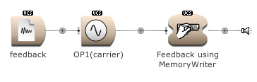
By routing back a signal to itself we can create noise and is called
feedback.
For this, the use of a
MemoryWriter
module is necessary [or by using a
FeedbackLoopInput
and
FeedbackLoopOutput pair].
The information, written into the memory location, is read by the
Sample player
module. Check the box for FromMemoryWriter
in the
Sample module.
(Open FM Basic
10.kym).
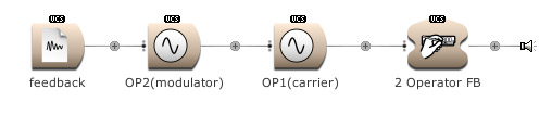
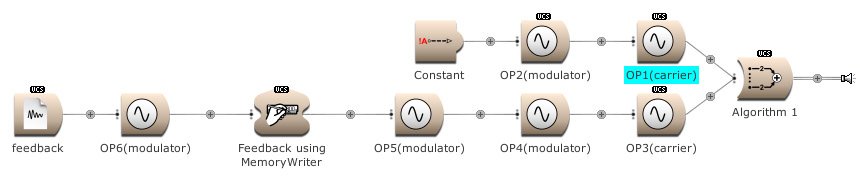
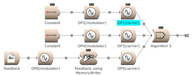
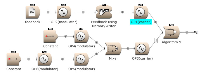
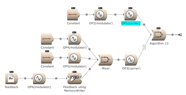
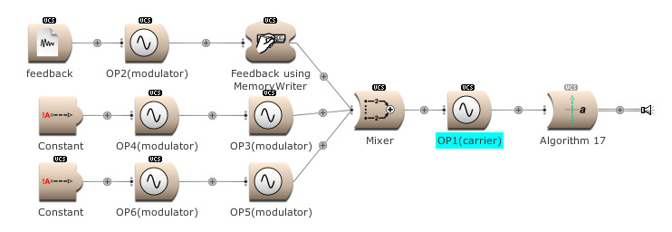
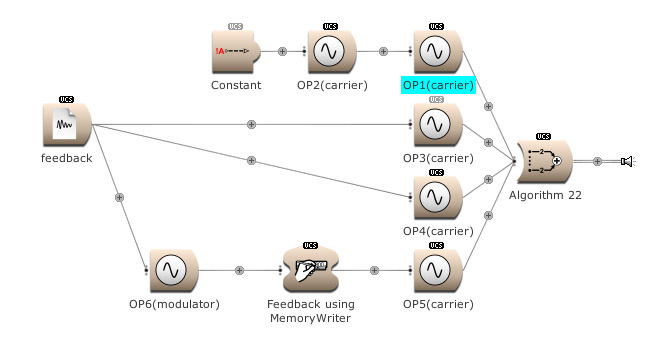
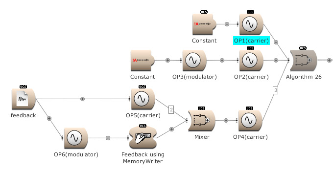
Connections in the Algorithm
Feedback can be used over several operators. Here
OP2
modulates
OP1.
The output of
OP1 is written into the memory
[for feedback]
and is modulating
OP2.
(Open FM Basic
11.kym).
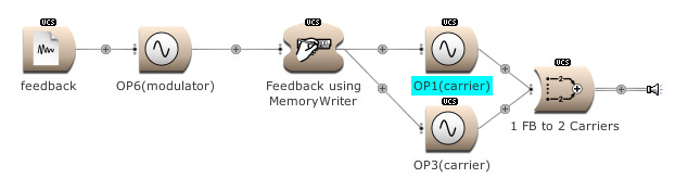
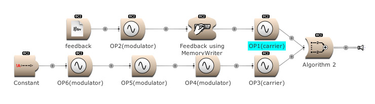
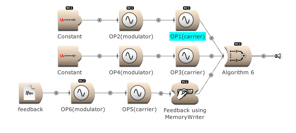
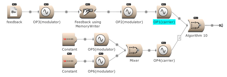
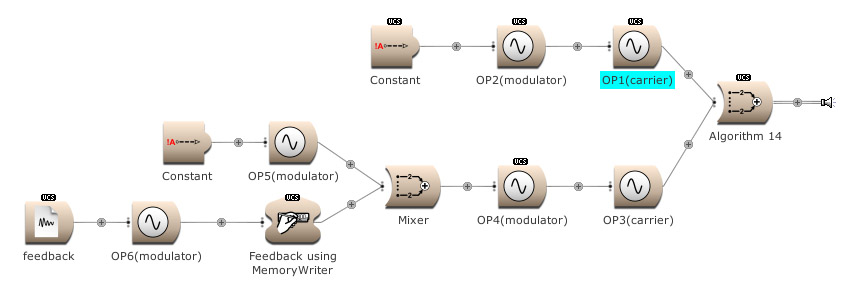
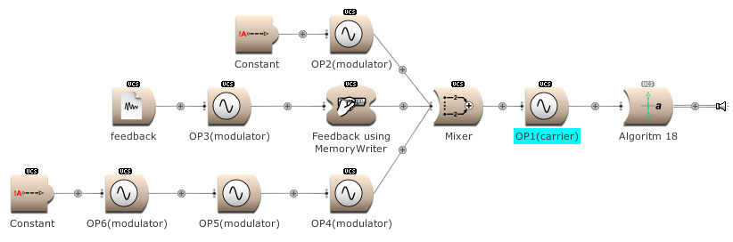
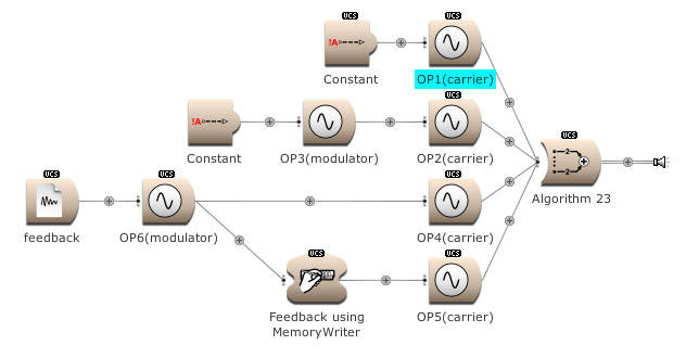
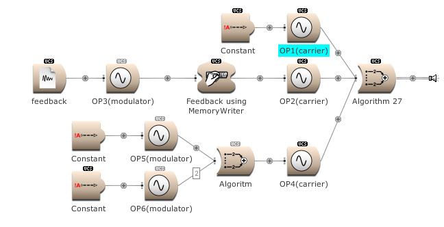
The modulator’s output, and feedback, can be used to
modulate several Operators. (Open FM Basic 12.kym).
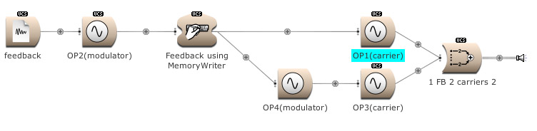
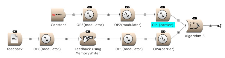
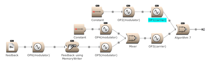
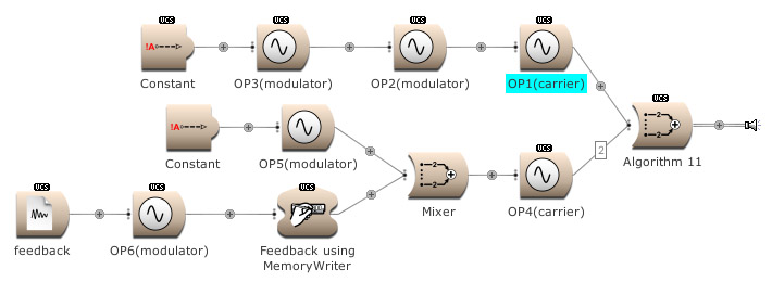
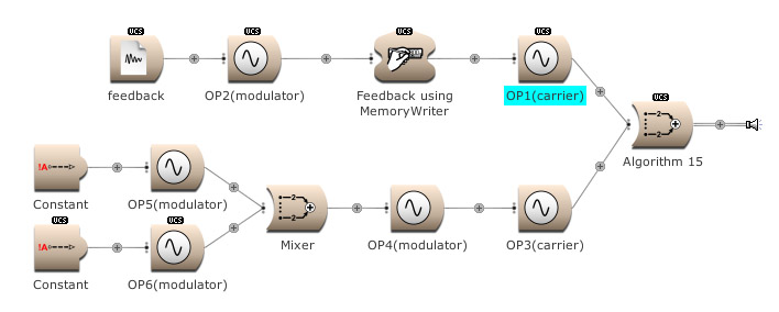
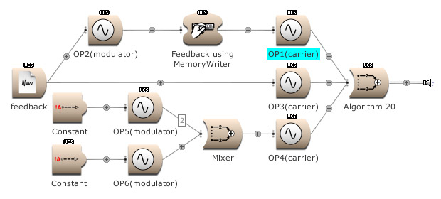
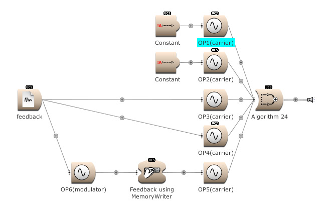
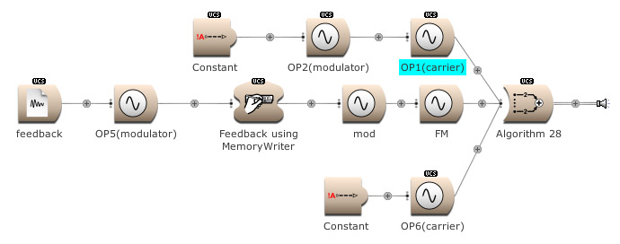
The feedback output is used directly on Op 1
and indirectly (via Op 4) on Op 3.
(Open FM Basic 13.kym).
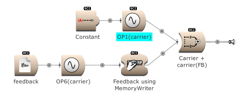
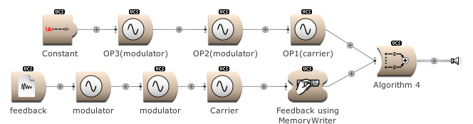
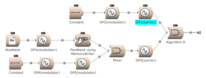
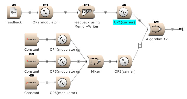
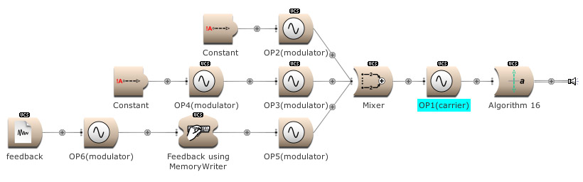
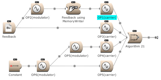
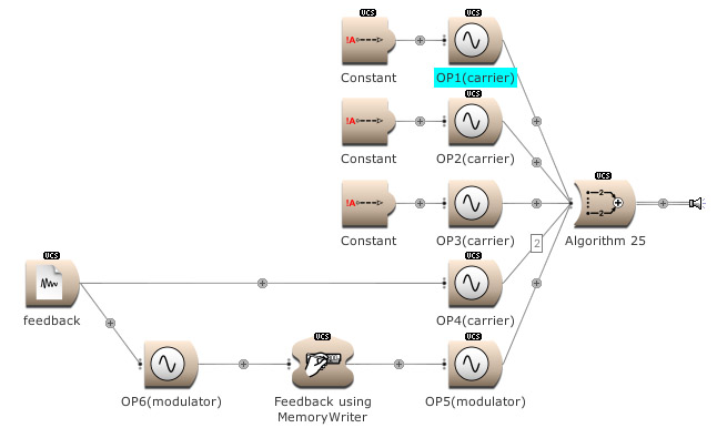
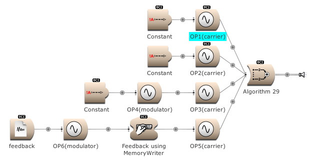
A sine wave combined with noise. (Open FM Basic
14.kym).
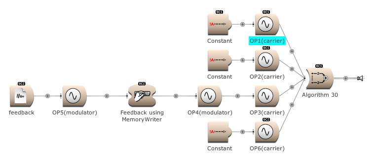
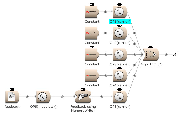
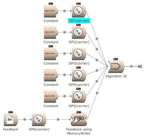
I hope you have enjoyed Part I.
In the archive in the Community Library, I have included
the 32 DX7 algorithms as a kind of ‘static Sound photo album’,
without any amplitude modulations other than the amplitude faders of the
Indexes. In my next article there will be more exploration of these algorithms…
© Roland Kuit 2016
32 algorithms:


Kyma™ is a registered trademark of Symbolic Sound
Corporation
Copyright © 2012 - 2021 Roland Emile Kuit. SONIC CULTURES LAB
-
SONIC SPACES, Laboratory of Patching and SoundLab are trademarks of Roland Emile Kuit.
All Rights Reserved.
Unauthorized duplication and distribution of copyrighted material
violates Federal Law.
This website collects no personal data.